لحام أقفاص حديد التسليح للأنابيب الخرسانية: التصنيع الآلي، وتفاوتات الخطوة، ومواصفات ASTM C76
كيف تحقق ماكينات لحام الأقفاص الحلزونية بنظام CNC سلامة نقاط اللحام، وانعدام الالتواء، وتوزيع التسليح بدقة.
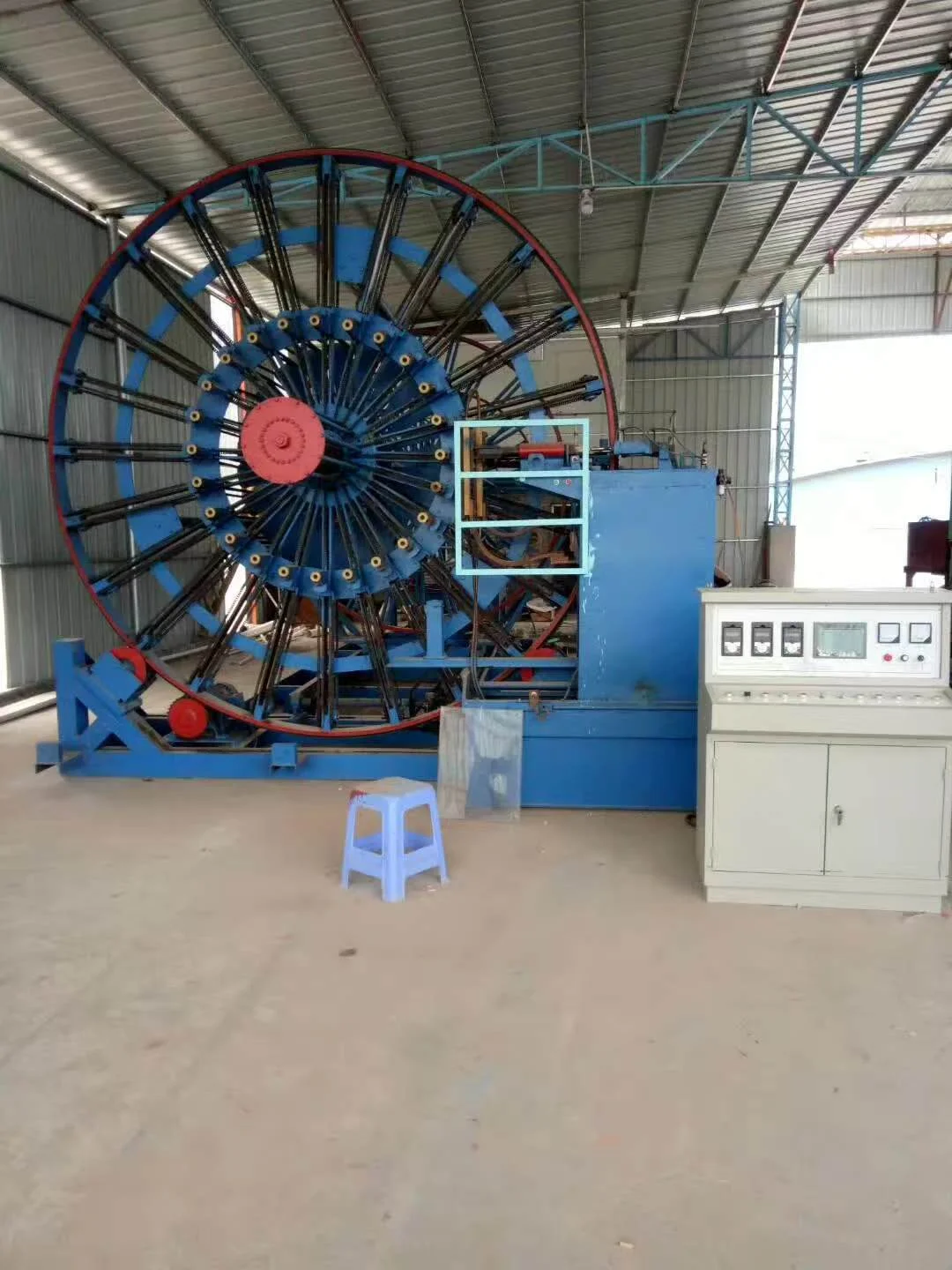
تعتمد السلامة الإنشائية تحت اختبارات التحميل D-load وفق ASTM C76 على دقة قفص التسليح. تعرف على كيفية قيام ماكينات اللحام الآلية بنظام CNC بضبط خطوة اللحام واستبعاد عيوب الربط اليدوي.
1. Why Cage Precision Dictates Pipe Load Capacity
In reinforced concrete drainage and sewer pipes, concrete excels in compression while steel reinforcement carries critical tensile stresses induced by backfill soil loads and heavy vehicular traffic. A misaligned cage, uneven helical pitch, or defective weld joints directly compromise the 0.3 mm crack test and ultimate crush resistance defined by ASTM C76 and GB/T 11836.
Manual cage tying is slow, labor-intensive, and inherently prone to spiral pitch irregularities. Modern precast pipe factories universally adopt CNC automatic steel cage welding machines to secure millimeter-level accuracy and robust structural integrity.
2. Automatic Resistance Roll Welding Mechanics
The CNC cage welder feeds cold-rolled ribbed rebar or hot-rolled wire from a decoiler. As the main drive faceplate rotates, the longitudinal bars are held securely in adjustable radial chucks. A traveling carriage advances synchronously, winding the circumferential spiral wire around the longitudinal bars.
At every intersection, an automatic pneumatic welding electrode applies focused pressure and delivers an instantaneous medium-frequency resistance pulse. The steel heats to forging temperature without melting through, creating a solid metallurgical bond.
3. Allowable Dimensional & Pitch Tolerances
| Inspection Parameter | Industrial Standard Tolerance | Factory Quality Control Target |
|---|---|---|
| Cage Inner Diameter (ID) | +5 / -0 mm | +3 / -0 mm |
| Cage Outer Diameter (OD) | 卤5 mm | 卤3 mm |
| Overall Cage Length | +5 / -10 mm | 卤5 mm |
| Helical Spiral Pitch Error | 卤5 mm over 10 consecutive wraps | 卤3 mm continuous |
| Longitudinal Bar Spacing | Max variance 鈮?40 mm | Max variance 鈮?20 mm |
| Longitudinal End Projection | Max 15鈥?0 mm beyond spiral wire | Max 10 mm cleanly trimmed |
| Weld Cross-Section Loss | Maximum 10% reduction | Kept under 5% via current modulation |
4. Bell and Spigot End-Ring Densification
The ends of reinforced concrete pipes endure intense shear stresses during installation and handling. Under industrial manufacturing rules, the automatic welding program must execute 'dense double-loop wraps' (瀵嗙剨鍙岀幆):
鈥?Both the socket/bell end and spigot end must be wrapped with at least two complete 360-degree closed circular loops with zero pitch spacing.
鈥?Diagonal cross-brace ties (鏂滄媺绛? are welded across the leading edge to prevent cage deformation when hoisted by forklift or gantry crane.
5. Placement of Rebar Spacers & Concrete Cover
Without adequate concrete cover depth, reinforcing steel is susceptible to groundwater chloride corrosion and carbonation. Precision-formed steel or polymer spacer clips must be attached around the cage periphery:
鈥?Layer-to-layer clips (灞傞棿鍗″瓙) maintain uniform concentric spacing in double-cage pipes (inner cage and outer cage) with height tolerance 卤2 mm.
鈥?Cover depth clips (淇濇姢灞傚崱瀛? must bear firmly against the internal surface of the steel mold, guaranteeing a minimum concrete cover of 20鈥?5 mm.
6. Tensile & Weld Joint Testing Protocols
Destructive weld testing is conducted on test specimens every production shift:
1. Cross-Weld Tensile Test: The welded joint must exhibit a tensile strength failure in the parent metal, not in the weld nugget itself. The ultimate tensile strength reduction must not exceed 20%.
2. Repeated Bend Test: Rebar wires undergo 90-degree reverse bend testing (GB/T 238) to confirm zero micro-fracturing along the heated zone.
Planning a Concrete Pipe Manufacturing Project?
Our engineering team provides comprehensive turnkey plant calculations, foundation layout drawings, mold customization specifications, and commercial quotations within 2 hours.
مقالات فنية ذات صلة
تصنيع غرف التفتيش والمطابق الخرسانية مسبقة الصب: معايير ASTM C478 وصب القواعد المتجانسة
يجب أن تتحمل غرف التفتيش مسبقة الصب ضغوط التربة العميقة وتمنع تسرب المياه الجوفية. تعرف على تكوينات القوالب للقواعد، والحلقات، ومخاريط الانتقال المطابقة للمواصفة ASTM C478.
تصنيع أنابيب الدفع النفقي بدون حفر: تحمل قوى الدفع العالية، وقوالب الأطواق الفولاذية، ومعايير DIN EN 1916
تقضي تقنية الدفع النفقي بدون حفر على التعطيل السطحي لكنها تُخضع الأنابيب الخرسانية لقوى دفع هيدروليكية هائلة. احترف نسب خلط الخرسانة فائقة القوة وتصنيع قوالب الأطواق الفولاذية وفق DIN EN 1916.
عملية إنتاج الأنابيب الخرسانية بأسطوانة التعليق: الدليل الصناعي الشامل خطوة بخطوة
تعد ماكينات أسطوانة التعليق العمود الفقري لإنتاج الأنابيب الخرسانية المسلحة عالية الكثافة (DN300–DN2000). يغطي هذا الدليل تسلسل الإنتاج بالكامل من تدرج الركام ولحام الأقفاص بنظام CNC إلى دمك الأسطوانة والمعالجة بالبخار على 4 مراحل.